

Various types of cookies are used on our website (and on all other digital platforms including mobile applications). View our new THE INFORMATIVE TEXT ON LPPD AND PRIVACY here. Google Analytics Analytical cookies help us to improve our website by collecting and reporting information on its usage. Google AdWords ve Remarketing We use marketing cookies to help us improve the relevancy of advertising campaigns you receive.
I have read the above articles
 INDEX
INDEX
 |
 |
 |
 |

NOTE: Device Functionality may change based on pre installed firmware
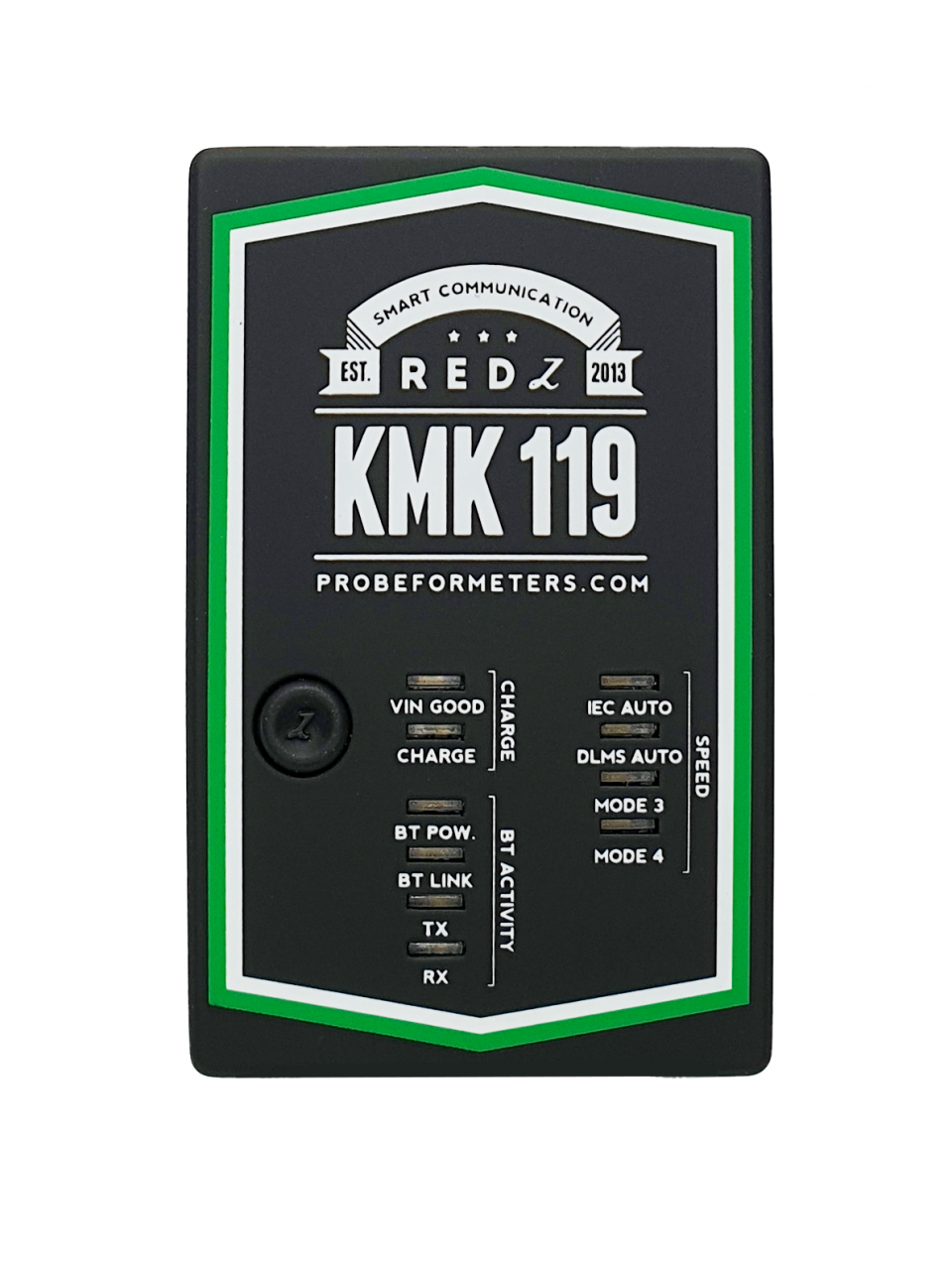
There are 4 operating modes for KMK118:
• Mode 1: 300-7E1 IEC auto Mode C.
• Mode 2: 300-7E1 IEC start and change to DLMS/COSEM ( 300-8N1 IEC start version also available which is needed for some meter applications)
• Mode 3: Fixed 9600-8N1 communication
• Mode 4: Custom command mode. In this mode the device will work transparently and gets some commands from user.
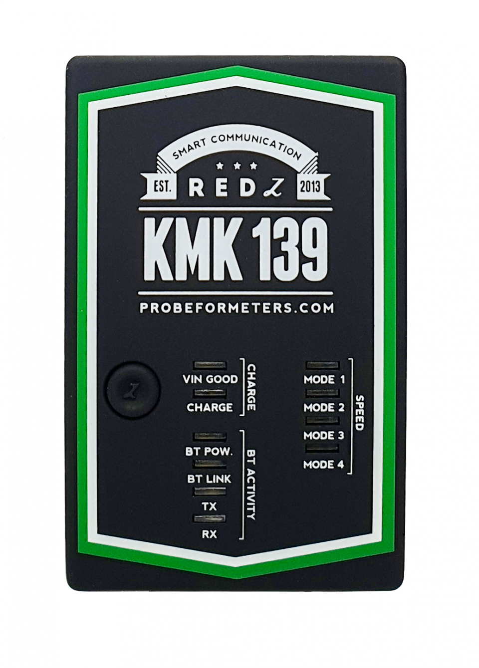
There are also 4 operating modes for KMK138:
• Mode 1: Fixed 4800-8N1 communication
• Mode 2: Fixed 9600-8N1 communication
• Mode 3: Fixed 19200-8N1 communication ( Fixed 28800-8N1 communication is available based on customer request)
• Mode 4: Custom command mode. In this mode the device will work transparently and gets some commands from user.
Firmware change can be done in field via using abcZ software and firmware supplied from our company. Check relevant section for firmware change procedure.
 |
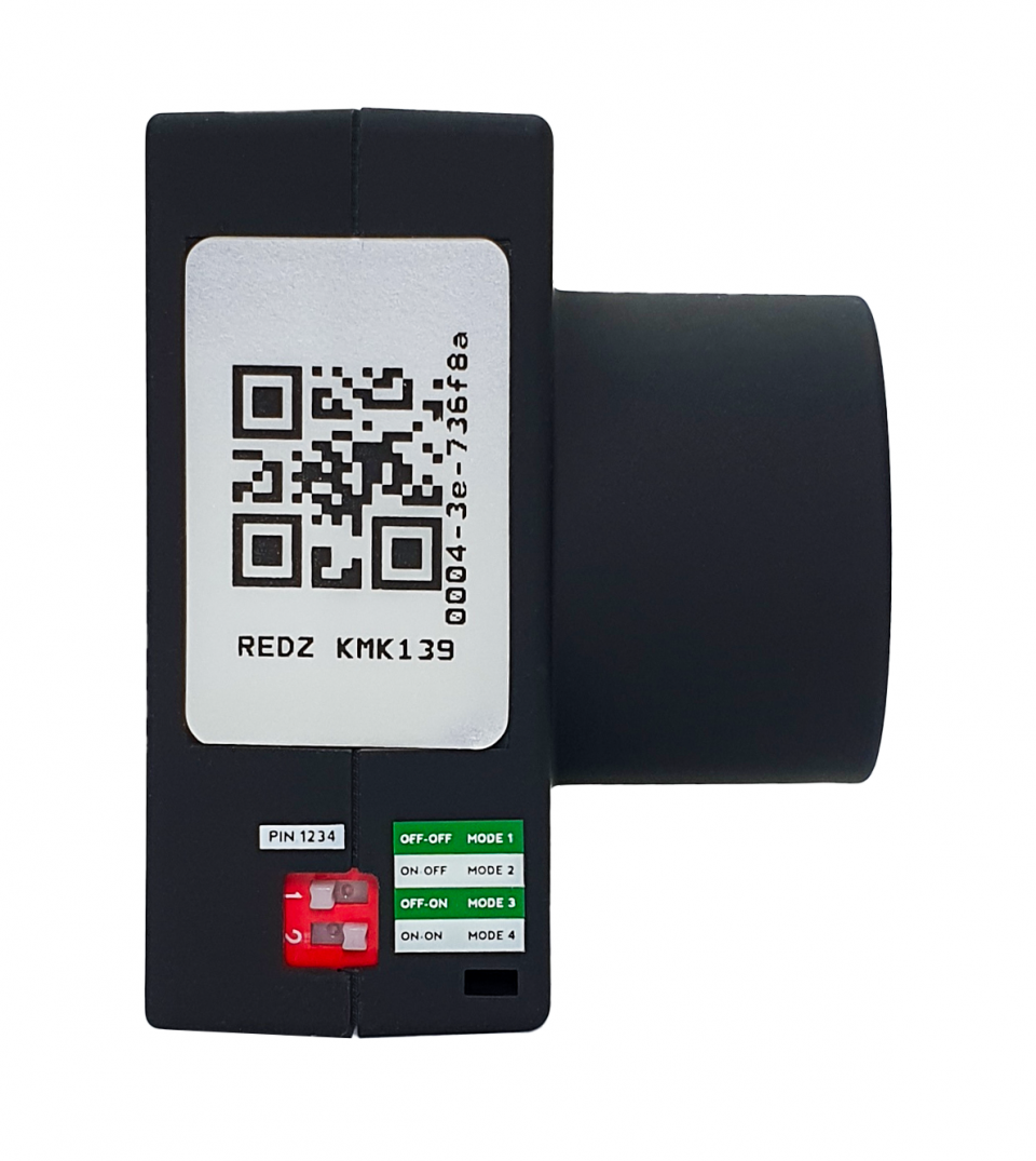 |
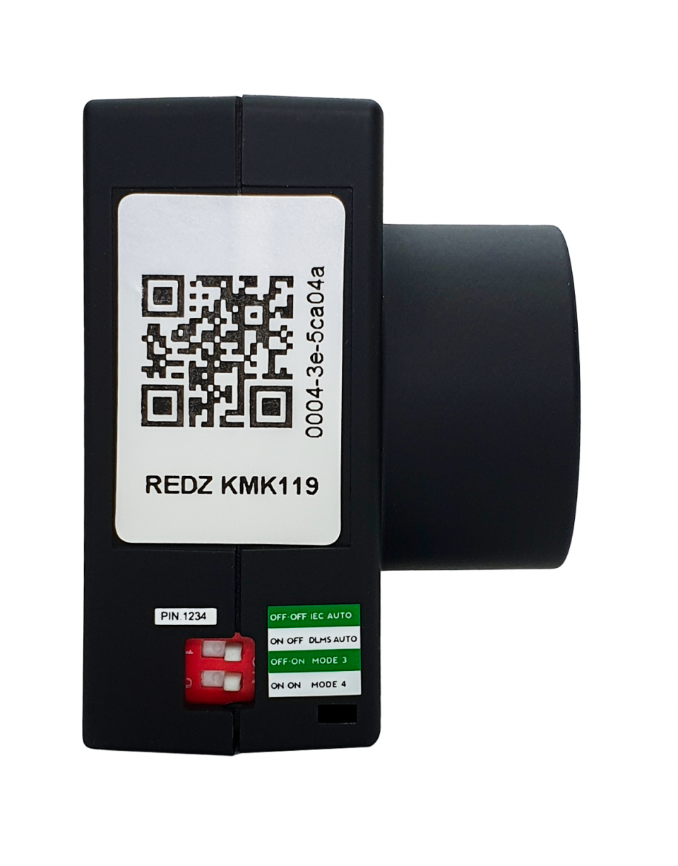
| Switch 1 | Switch 2 | Mode | Mode Function for KMK119 | Mode Function for KMK139 |
| OFF | OFF | Mode 1 | 300-7E1 IEC auto Mode C. Auto baud change based on protocol |
Fixed 4800-8N1 communication |
| ON | OFF | Mode 2 |
300-7E1 IEC start and change to DLMS/COSEM ( 300-8N1 IEC start version also availabel which is needed for some meter applications) Auto baud change based on protocol |
Fixed 9600-8N1 communication |
| OFF | ON | Mode 3 | Fixed 9600-8N1 communication | Fixed 19200-8N1 communication ( Fixed 28800-8N1 communication is available based on customer request) |
| ON | ON | Mode 4 | Custom command mode. In this mode the device will work transparently and gets some commands from user. | Custom command mode. In this mode the device will work transparently and gets some commands from user. |
NOTE: Switch change will be aplied on next Power ON of the device. So in order to change working mode, user has to turn off the probe first.
NOTE: Project specific firmware available based on customer specific needs. Please contact our company for your needs.
 |
 |
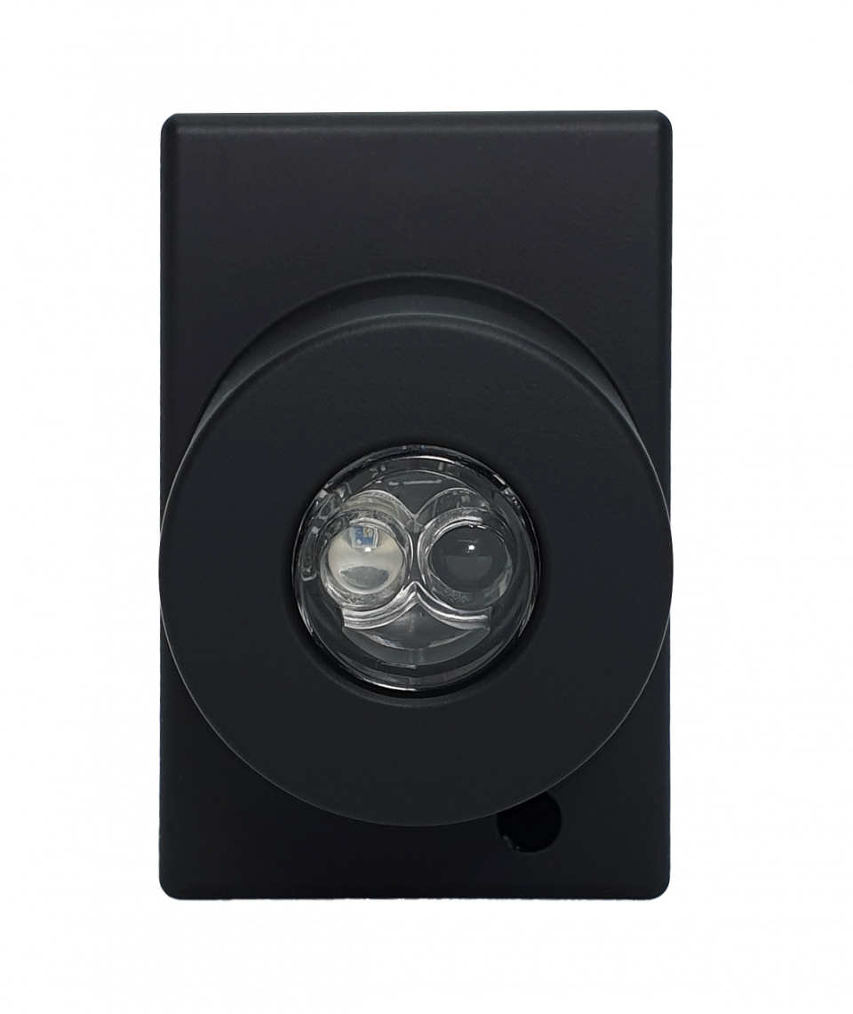
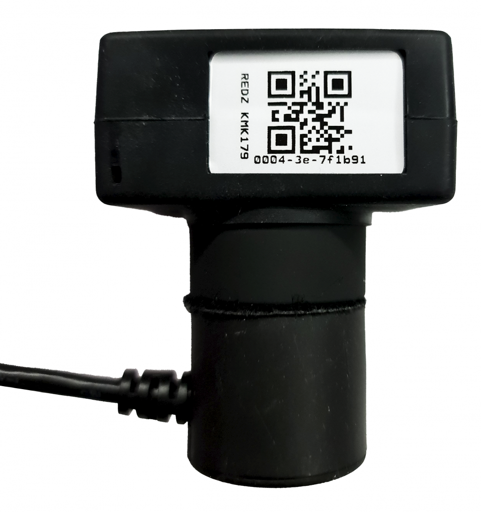
Probe comes with relavant interface
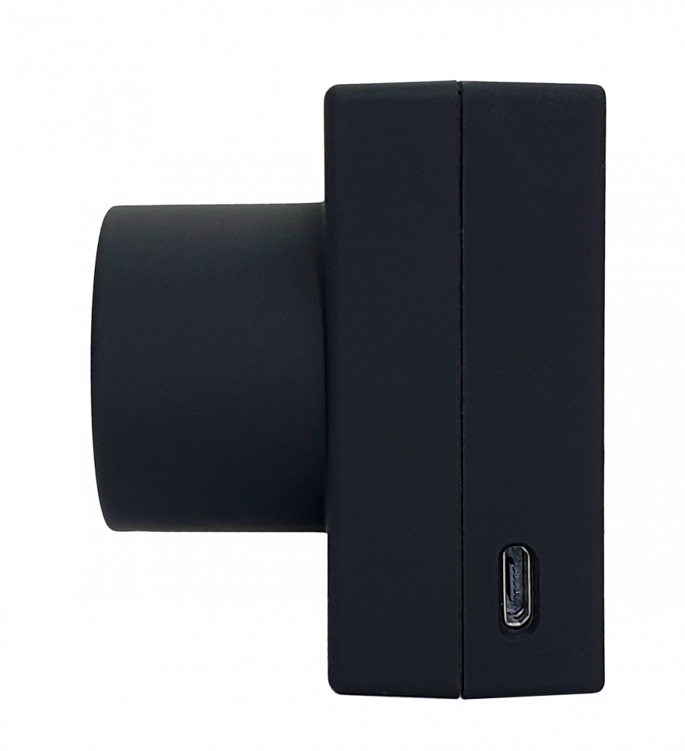
KMK119 is an IEC probe: it has flat interface to be placed on the meter probe interface
KMK139 is an ANSI probe: it has cavity in probe interface part to fit the meter probe interface
NOTE: All KMK probes uses N38 magnet in order to to better attach to meter
 |
 |
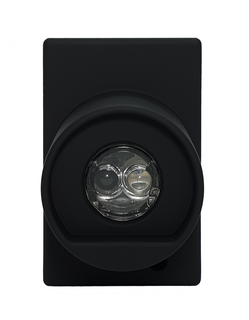
Probe comes with relavant interface
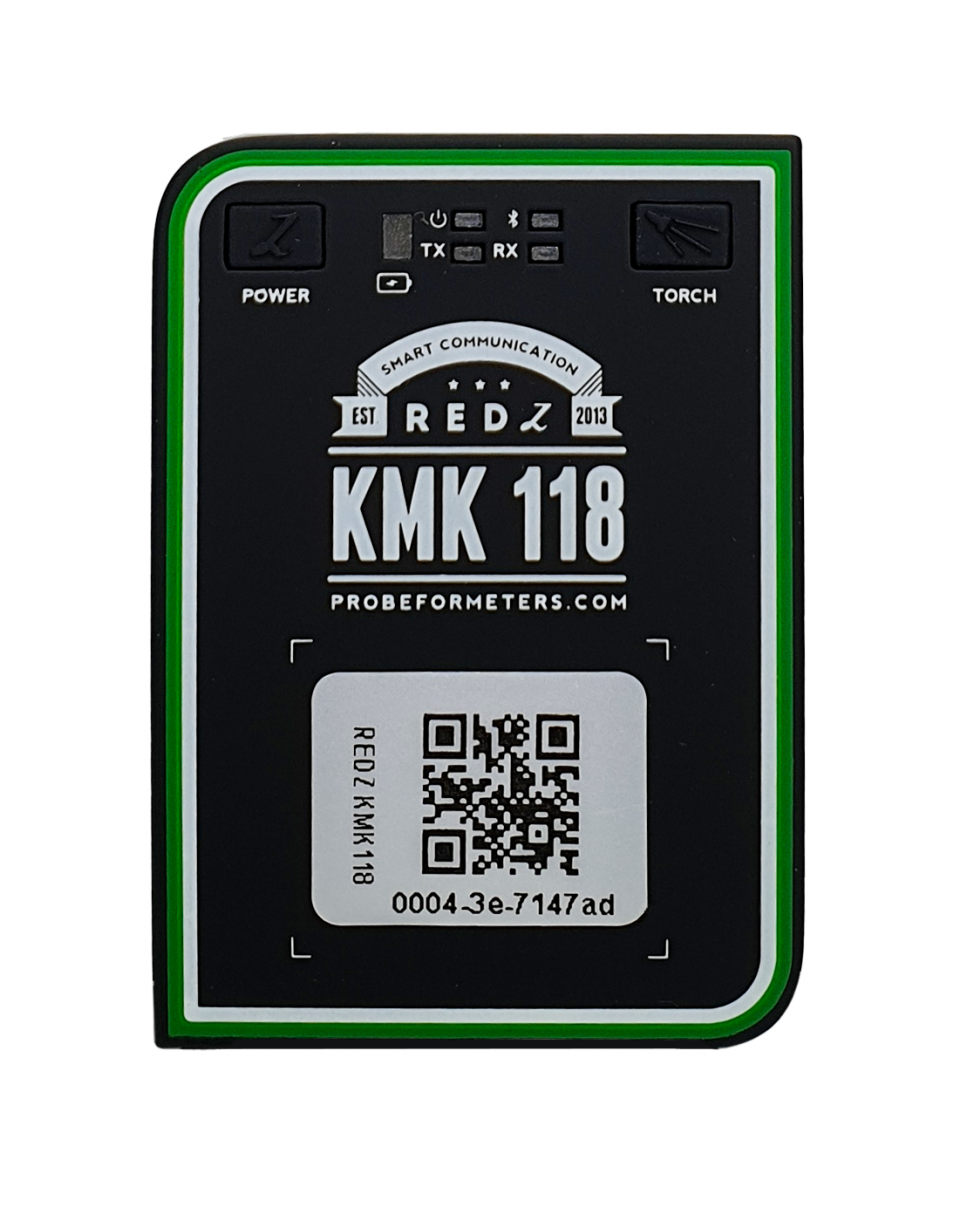
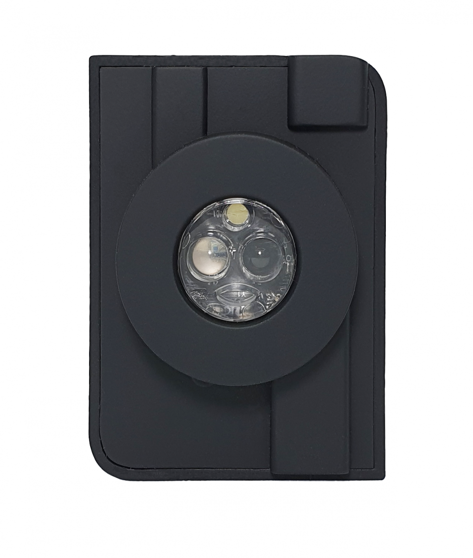
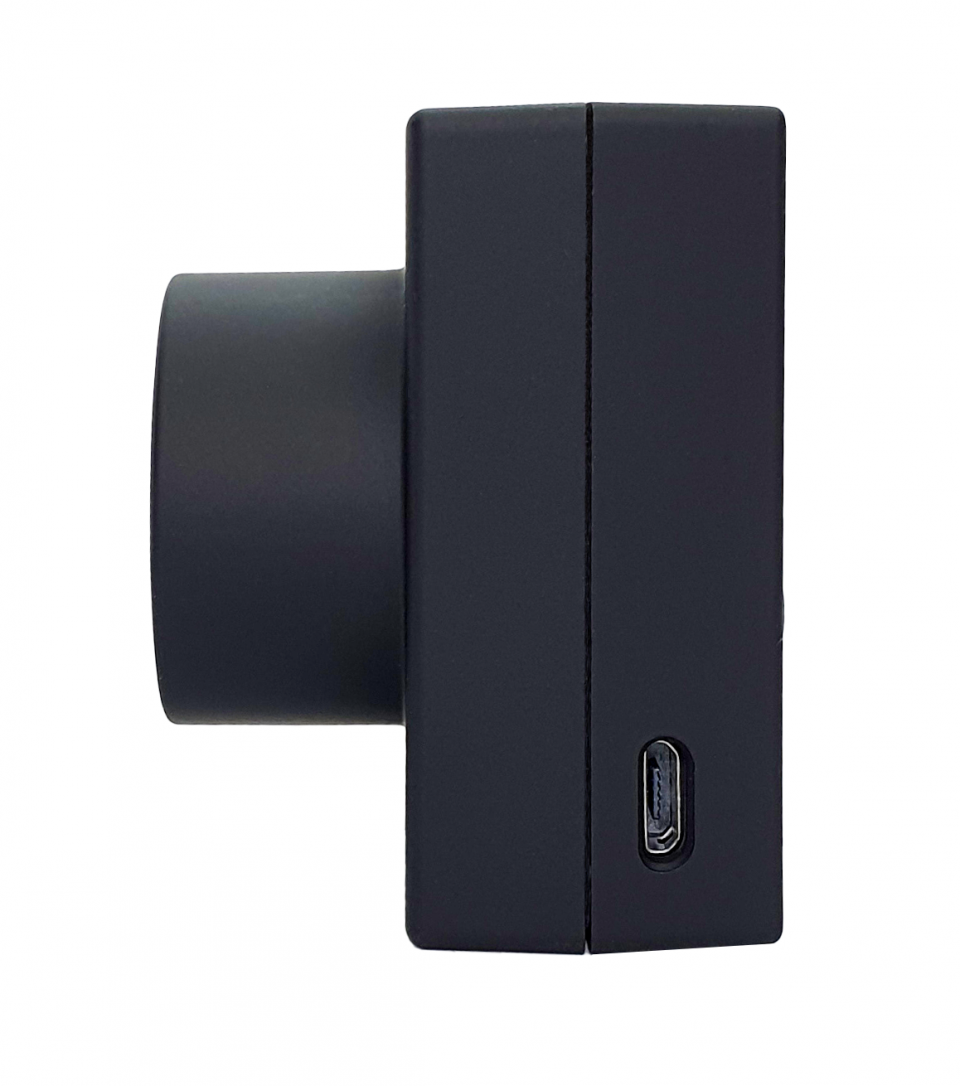
KMK118 is an IEC probe: it has flat interface to be placed on the meter probe interface
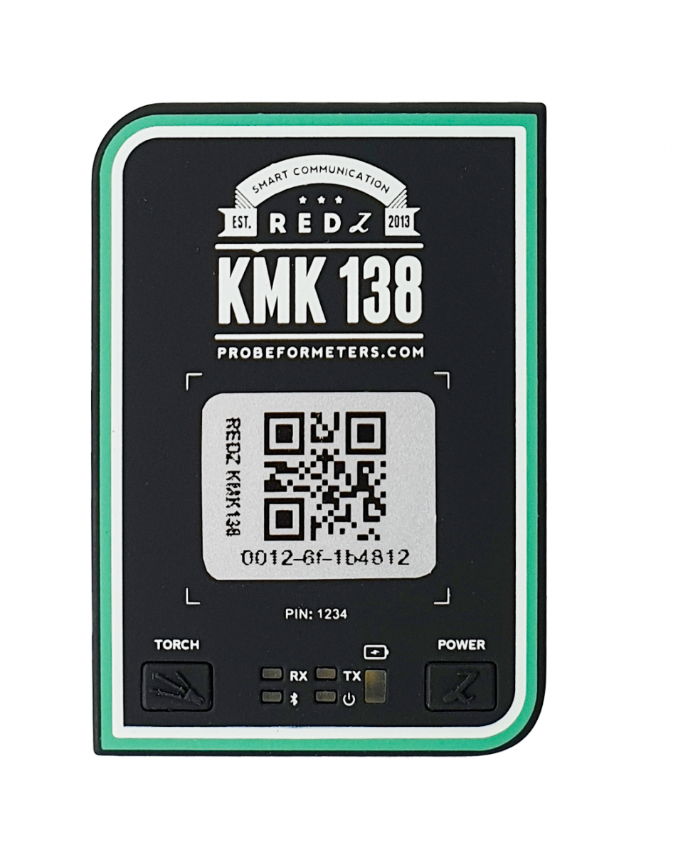
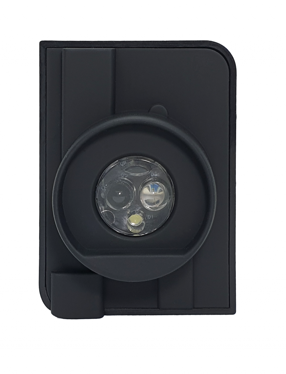
KMK138 is an ANSI probe: it has cavity in probe interface part to fit the meter probe interface
NOTE: KMK118 and KMK138 has built in torch. It can be used to light up the display of meters during manual reading in the field.
NOTE: All KMK probes uses N38 magnet in order to to better attach to meter
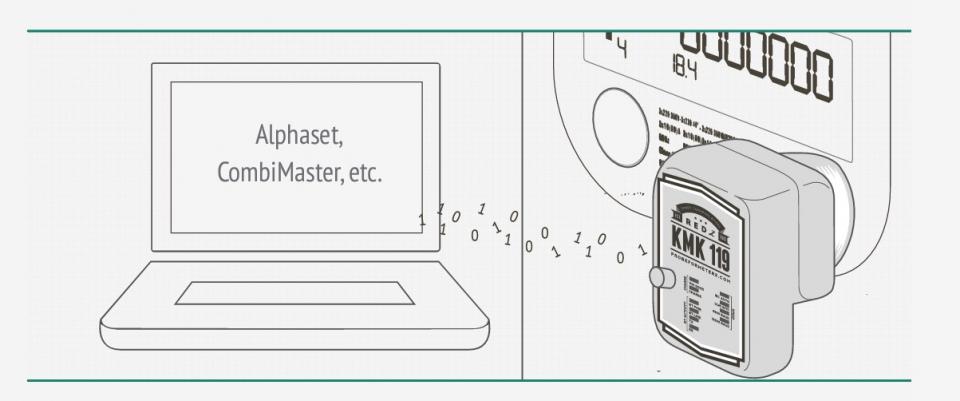
In this mode the probe can automatically detect IEC 62056-21 Mode C (formerly known as IEC1107) protocol and make necessary baud change overs automatically. This mode is designed so that any software that can read IEC62056-21 meters with cable version of optical probe can instantly use Bluetooth version of probe. After paring the probe the already available software can instantly use this mode to read meters such as Elster, EMH, L&Gyr etc.
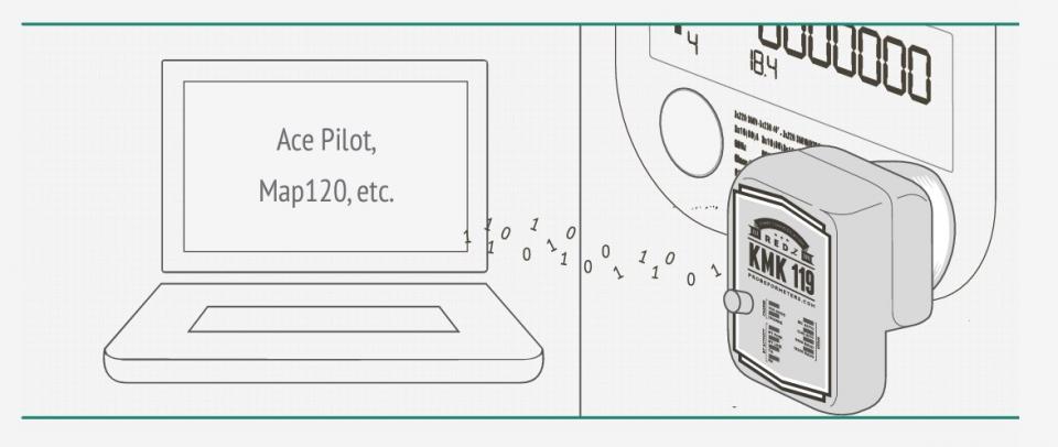
In this mode the probe can automatically detect IEC 62056-21 Mode C ( formerly known as IEC1107) opening on DLMS/COSEM protocol make necessary baud and data type change overs automatically. This mode is designed so that any software that can read DLMS/COSEM meters with IEC opening mode with cable version of optical probe can instantly use Bluetooth version of probe. After paring the probe the already available software can instantly use this mode to read meters such as Itron, L&Gyr etc.
This is fixed speed and data type communication mode. This can be used in IEC870-5-102 standard or in any standard that is necessary to communicate in this data type and baud rate.
In this mode the device will work transparently and can be managed by special commands. Command mode is the best solution if the user is capable of editing or developing their own meter reading software so that user can use Bluetooth Probe for communication.

NOTE: The C# code example for sending command is as follows:
////=======================================
//Initialize Probe at baudrate 300
buffer = new byte[] { 0xFE, 0xFE, 0x42, 0x4C, 0x55, 0x45, 0x30, 0x38, 0x4E, 0x31, 0x30, 0xFF };
this.comport.Write(buffer, 0, buffer.Length);
Thread.Sleep(50);
//Sleep is important, also it issuggested to wait 1000ms after opening the TCP port.
////=======================================
This command will change baud rate or data type.
Second char from last can vary so that user can send different commands to probe:
0x30 : 300 baud
0x31 : 600 baud
0x32 : 1200 baud
0x33: 2400 baud
0x34: 4800 baud
0x35: 9600 baud
0x36:19200 baud
0x37: 28800 baud
0x38: 38400 baud
0x40: 7E1 data type
0x41: 8N1 data type
0x42: 8E1 data type
0x43: 8O1 data type
0x44: 8N2 data type ( available after v5.2 firmware)
0x50: Break State: Enter
0x51: Break State: Exit
0xA0: Firmware Version Query The firmware version information will be sent and data will be terminated with 0x00 character.
0xA1: Battery Voltage Query (mV) Battery voltage information will be sent and data will be terminated with 0x00 character.
0xA2: Close Sleep Timer (10 seconds) If there is no connection with the probe for more than 10 seconds, the port goes into sleep mode and power saving mode will be on. When the Bluetooth connection is established, the sleep mode will be off and the port will work as usual and user operation is not affected by this process. Confirmation information will be sent and data will be terminated with 0x00 character.
0xC2: Shut Down The Probe Using this command, the power can be turned off as if the optical probe was closed by the power button.
0xC3: Auto Shutdown Timer Setting A time interval between 0 to 254 seconds should be set (in HEX format). If there is no communication with the probe after that time interval, the device will be turned off (probe shuts down). This can prevent the probes to be left forgotten with power on for long time and consume battery. The default value is 254 seconds. This feature can be disabled by setting value 255. After sending the command, confirmation information will be sent and data will be terminated with character 0x00. Then the time interval must be set. The next confirmation information will be terminated with character 0x00 again.
0xD0: Probe Reading Sensitivity Setting If user gets some meaningless or corrupted data or no data at all while reading the meter, it is possible to change the reading accuracy of the probe and make special setting based on meter type to prevent reflections or light interferences or increase sensitivity for weaker meter reasponse. A value between 0 to 255 should be set (in HEX format). Usually maximum value cannot exceed 0x55 in order to prevent reflection on KMK119 side.
As this value increases, sensitivity of the probe and light reception capacity increase. The default value is 26 (0x1A). After sending the command, confirmation information ACK: 0x06 will be sent and data will be terminated with character 0x00. Then the sensitivity value must be set. The next confirmation information ACK: 0x06 will be terminated with character 0x00 again. Then communciation can continue as it is.
Example:
-> 0xFE 0xFE 0x42 0x4C 0x55 0x45 0x30 0x38 0x4E 0x31 0xD0 0xFF
<- 0x06 0x00
-> 0x1A
<- 0x06 0x00
If the meter is operated by battery and has weaker communciation channel then sensitivity must be increased, sensitivity value can be increase 1 by 1 and correct point can be found.
If the there are reflections and duplicated bytes when meter sending data then sensitivity must be decreased, sensitivity value can be decreased 1 by 1 and correct point can be found.
The user can transmit any data and command to the optical probe without any restrictions and can use the optical probe at any desired data type and communication speed at any time. The commands transmitted to the optical probe and the data transmitted to the meter is always separated.
WARNING: The default value for "Probe Reading Sensitivity Setting" was 49 (decimal) in old versions. Now it is 26 (decimal). Please update accordingly in your code if you are using latest versions now.
0xE0: Save Settings. It is possible to save settings for following data Sleep Timer, Auto Power seconds, Reading Sensitivity, Baud Rate and Data type. After sending the command, confirmation information will be sent and data will be terminated with character 0x00. All listed values are saved as it is set and next time the device restarted they will be used based on saved values.
0xE1: Restore Factory Defaults ( available with v3 designs and later) Command sets values as follows and saves them
• Sleep Timer: ON
• Auto Power Down Seconds : 254
• Reading Sensitivity: 26
• Baud Rate: 300
• Data Type: 7E1 After sending the command, confirmation information will be sent and data will be terminated with character 0x00.
NOTE: The modes can be changed via switch in KMK119. KMK118 needs firmware change to operate in different modes.
This is fixed speed and data type communication mode. This can be used in any standard that is necessary to communicate in this data type and baud rate.
This is fixed speed and data type communication mode. This can be used in any standard that is necessary to communicate in this data type and baud rate.
This is fixed speed and data type communication mode. This can be used in any standard that is necessary to communicate in this data type and baud rate.
This option can be selected to have 28800-8N1 data option.
In this mode the device will work transparently and can be managed by special commands. Command mode is the best solution if the user is capable of editing or developing their own meter reading software so that user can use Bluetooth Probe for communication.
Please see KMK118 & KMK119 Command Mode for details and usage.
NOTE: The modes can be changed via switch in KMK139. KMK138 needs firmware change to operate in different modes.
 |
 |
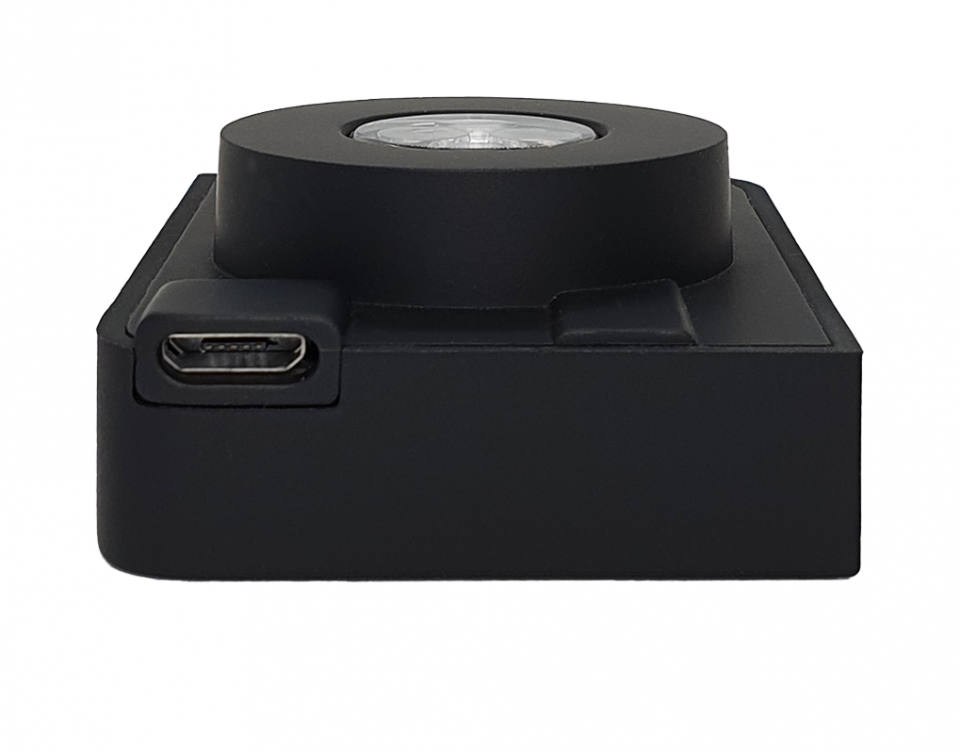
NOTE: Charge port can be Micro USB or USB Type C based on version of hardware. Probe comes with relevant charge cable and by using that cable probe can be charged with any PC or Phone charger that has USB Type A on it.
 |
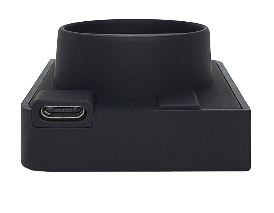 |
NOTE: Charge port can be Micro USB or USB Type C based on version of hardware. Probe comes with relevant charge cable and by using that cable probe can be charged with any PC or Phone charger that has USB Type A on it.
The probe gives a low battery warning via LEDs to warn the low battery status and remind user to recharge. When battery is low, "POW" LED turns into RED light and remains until it’s charged enough.
KMK119 and KMK139 uses a 1200mAh battery inside.
KMK118 and KMK138 uses a 600mAh battery inside.
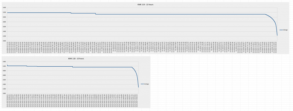
Here is a test result for battery using
This test has been done with a meter reading device that read an IEC meter in every 10 seconds ( after successfull readings). KMK119 and KMK139 is expected to work 22 hours with full charge and on non stop operation. KMK118 and KMK138 is expected to work minimum 10-11 hours with full charge and on non stop operation.
Details of test can be shared upon request.
The probe has capability to change firmware over wireless connection. This way the user can get latest updates of probe operation and also user may also ask for changes. Here are some examples:
• Firmware change for specific meter model and protocol
• Firmware change to disable switches and work only in command mode
• Firmware change to put any feature that user needs
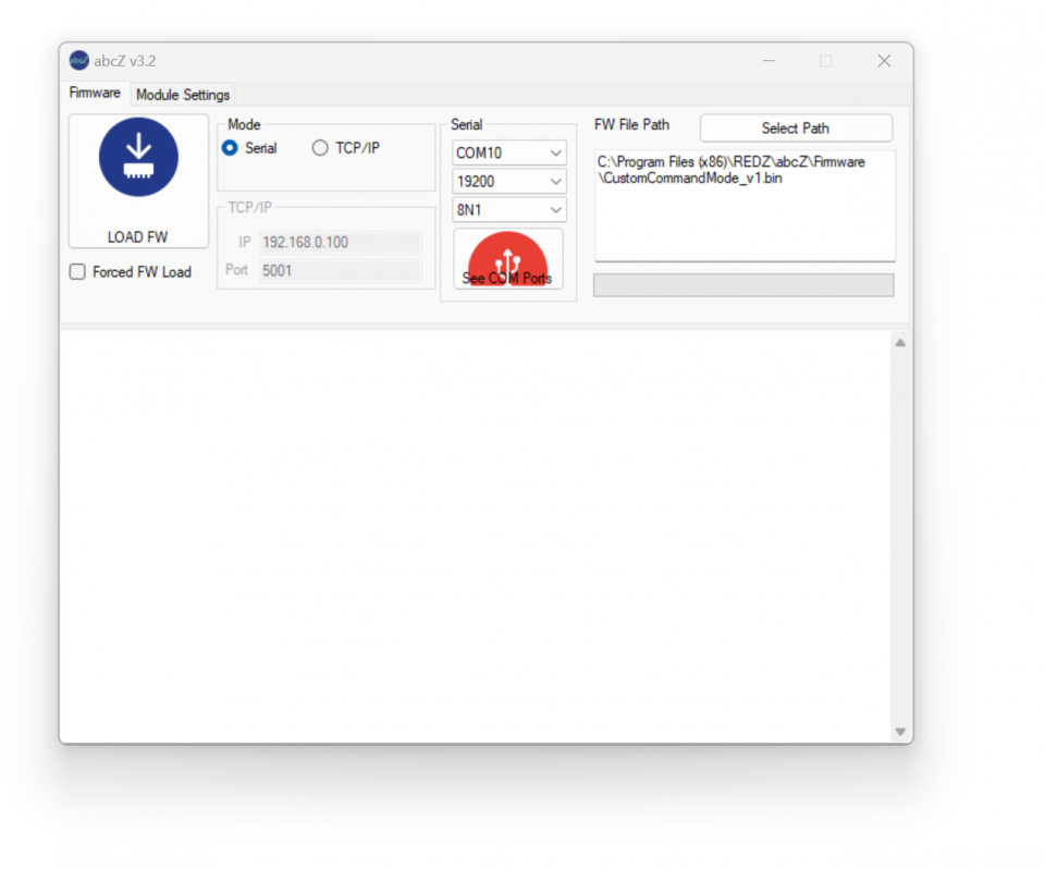
Firmware change procedure need specific frmware prepared by our company and the firmware upgrade software abcZ software also developed by our company. In order to use the software the specific firmware must be selected. After selecting the firmware path by clicking "Select Path" button the firmware can be loaded to probe.
NOTE: The probe has protection time window 10 seconds after the powered up so the process must be started within 10 seconds after probe powered up.
User should make serial connection with probe and click "LOAD FW" button using abcZ Software. The software will show the percentage of process visually in terms of number of sent data packages and that process can also be monitored by LEDs (work mode LEDs) on probe. Also power LED will blink RED during operation. (once %25 of process finished LED1 will be on and continue with LED2, LED3 and finish with LED4 after %100 finished). The process will take less than a minute and the probe will restart itself. Device should not be powered off during update process.
NOTE: If somehow the firmware upgrade process is interupted and upload file has failed, the probe will lose fimware and stay in bootloader mode. In that case user can try upgrading the firmware again and this time should mark the "Forced FW Load" check box.
Here is a video example on how to change firmware of KMK118 probe
Here is a video example on how to change firmware of KMK119 probe
If somehow the firmware upgrade process is interupted and upload file has failed, the probe will lose fimware and stay in bootloader mode. In that case user can try upgrading the firmware again and this time should mark the "Forced FW Load" check box. Here is a video example on how to force firmware change for KMK119 probe.
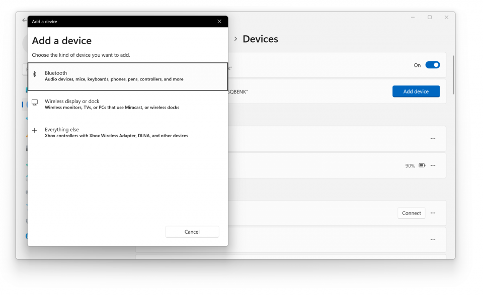
Enable Bluetooth feature of your PC. Then push the power button of Bluetooth Probe to power the device. Enter "Bluetooth & devices" setting on your PC.
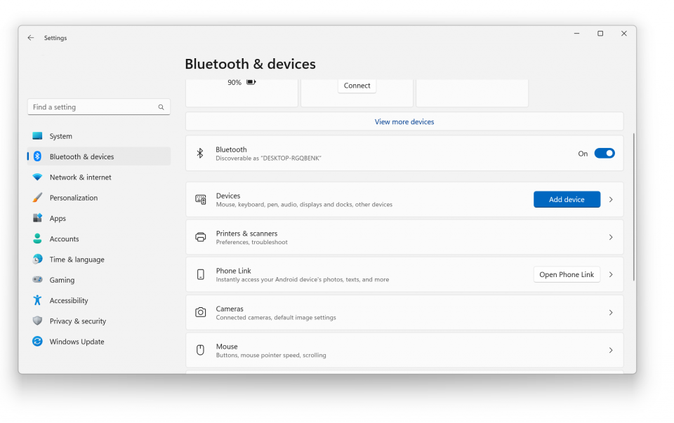
Click "Device" option and if not set, select "Advanced" for "Bluetooth Discovery Option".
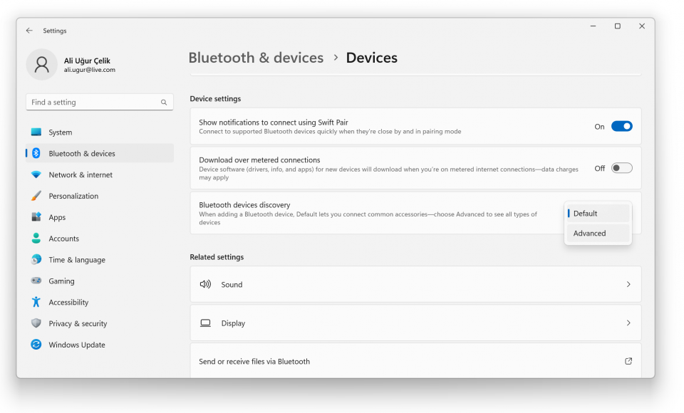
Go back to top of the page and click "Add Device" and select "Bluetooth".
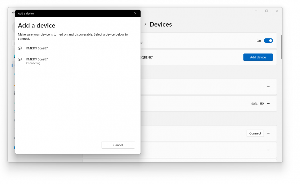
Select the Bluetooth probe from the list. Pc will connect and will create a Virtual COM port for this probe.
NOTE: If Bluetooth Low Energy (BLE) is enabled, you may see 2 devices in this list with same name. Please selest the one that do not asks for PIN. Other one is for BLE.
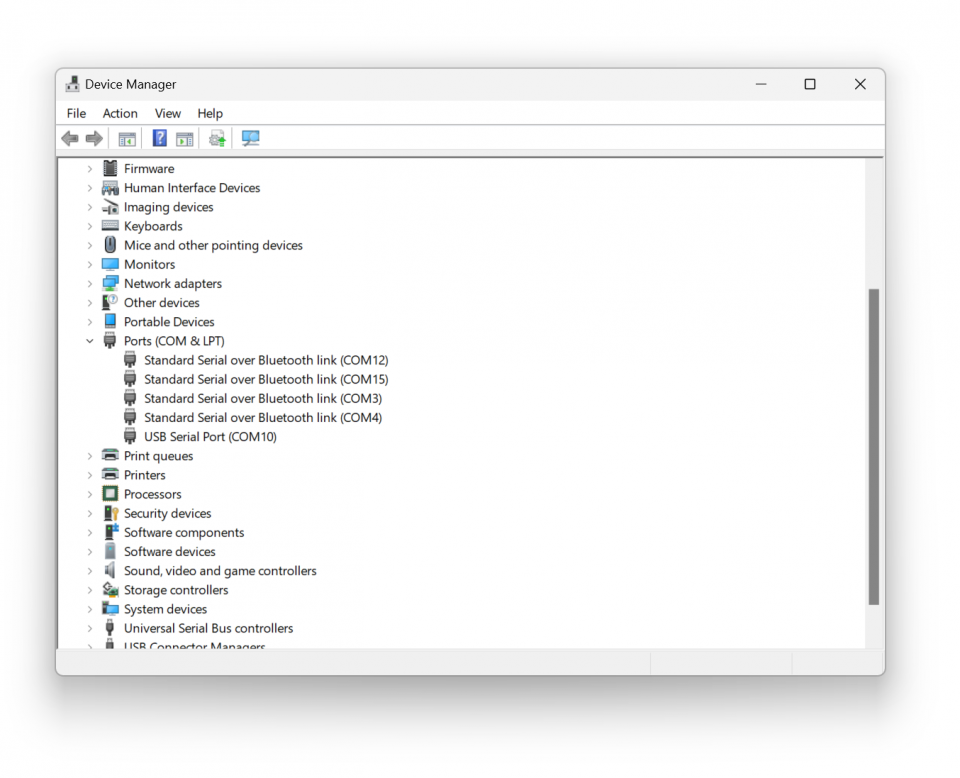
Once the device is added to your computer, there will be 2 COM ports created. In this example COM3 and COM4 created for PC. Please use COM port with small value which is COM3 in this example.
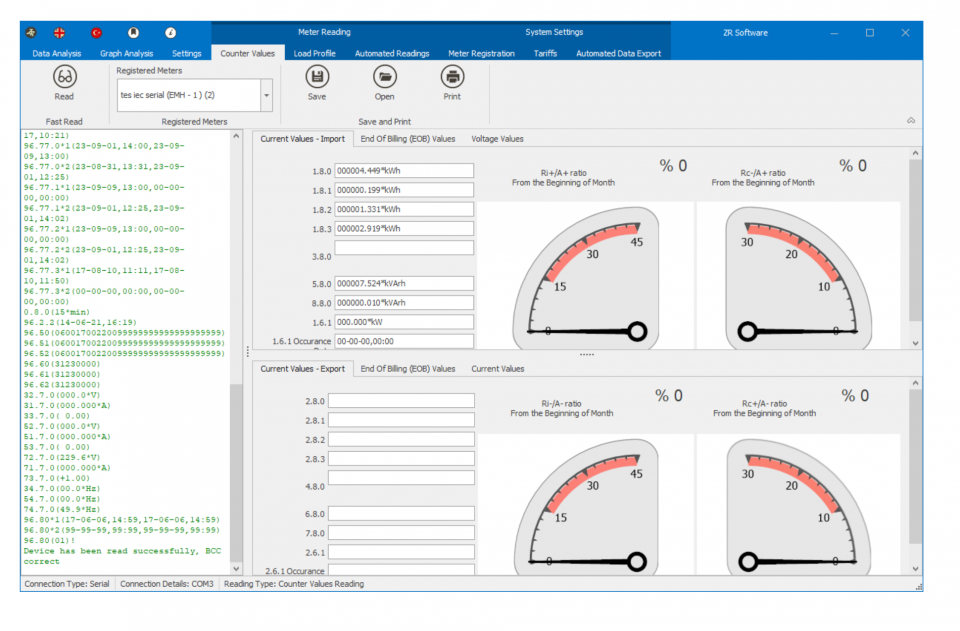
Here is example reading via ZR Software with COM port 3.
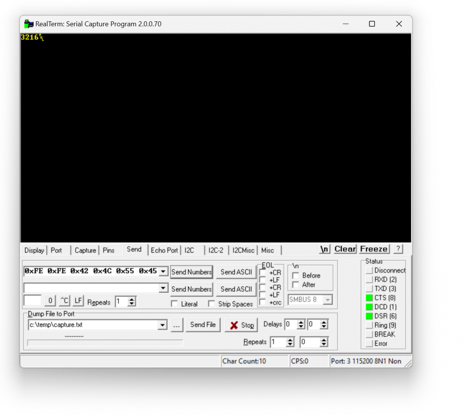
User can test Command mode of the probe with a terminal program. User should set the switch position to Mode 4 and power up probe before start testing.
In this example RealTerm ( free open source terminal) software has been used. Open terminal, select COM port of probe and click connect.
NOTE: Connection is available only after the correct paring of probe with your PC.
"Link" LED will turn ON continuously once the program connected to probe. Then user can communicate with the probe using different commands via terminal program.
For example to read battery voltage of the probe user can send following byte Array to probe:
0xFE 0xFE 0x42 0x4C 0x55 0x45 0x30 0x38 0x4E 0x31 0xA1 0xFF
Copy and paste this command to terminal and click "Send Numbers", Probe will answer with battery voltage in mV.
NOTE: Command byte is last byte before 0xFF. Other bytes are fixed and do not change. To query the battery voltage, the command byte should be 0xA1.
In order to configure Bluetooth settings, additional optical probe is needed. So user should use USB service probe and place them against to each other
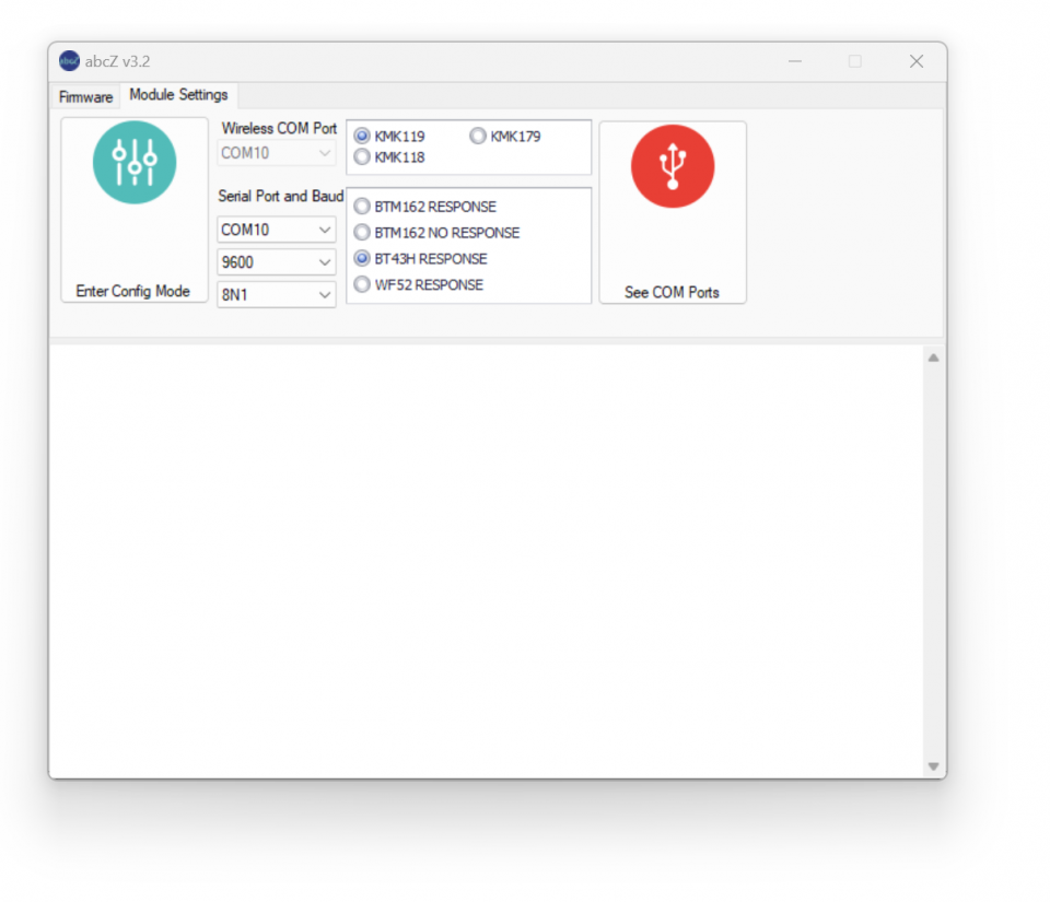
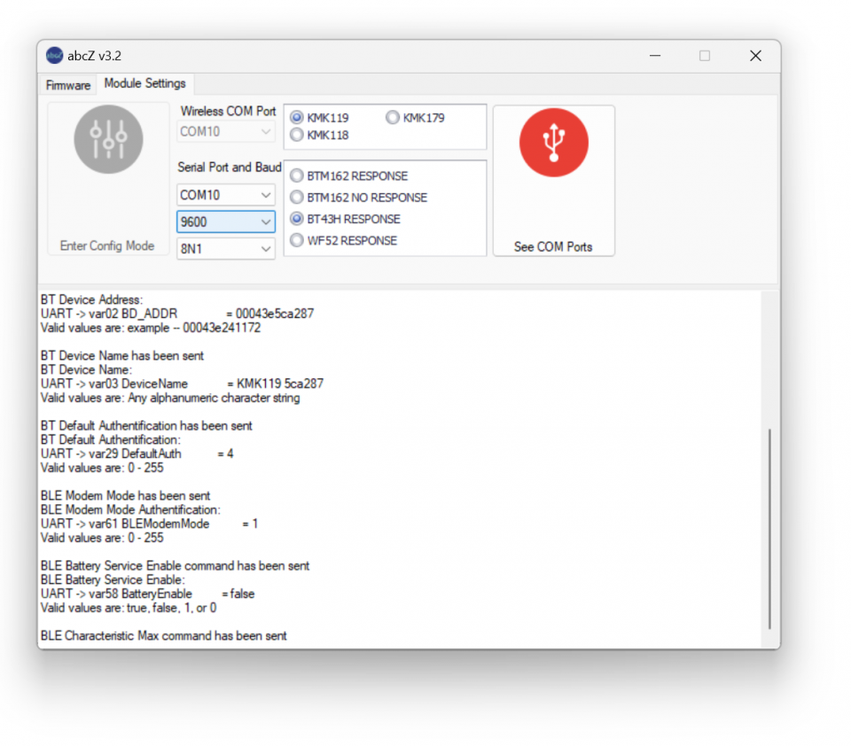
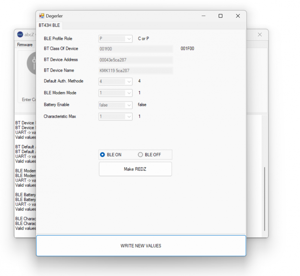
NOTE: Device will be ready for configuration once the settings page opened
NOTE: Click "Write New Values" when all settings are done. New settings will be written and device will restart. User can manually restart device as well.
After all settings done, user may use the probe as Bluetooth Low Energy Probe (BLE) in supported devices and applications.
(USB probe is still connected to PC and Bluetooth probe is still on top of it and set to Mode 3, no change untill now with hardware and software setup)
NOTE: Please do not forget to set switch settings to desired position before using the probe in normal operation and after configuration.
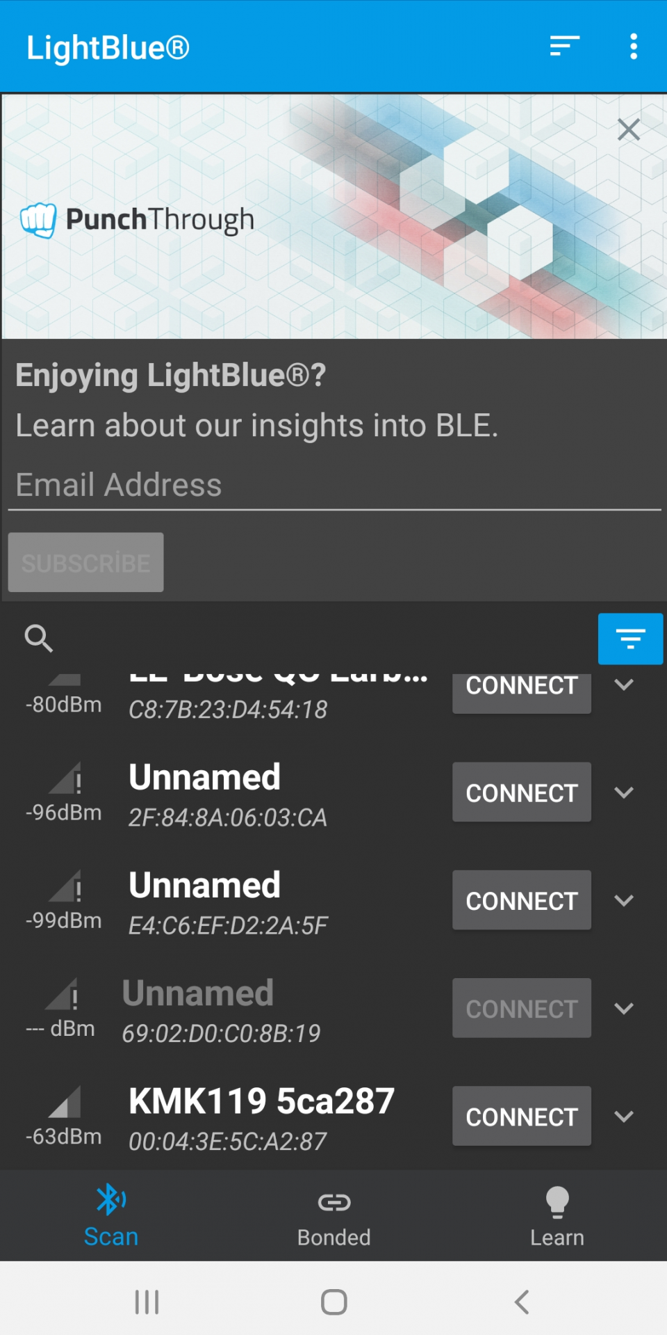
Here is example reading via "LightBlue" app available on Google Play for BLE test on Android devices.
Enable Bluetooth of your device and Open app. Select KMK Bluetooth Low Energy (BLE) Probe from list and click connect.
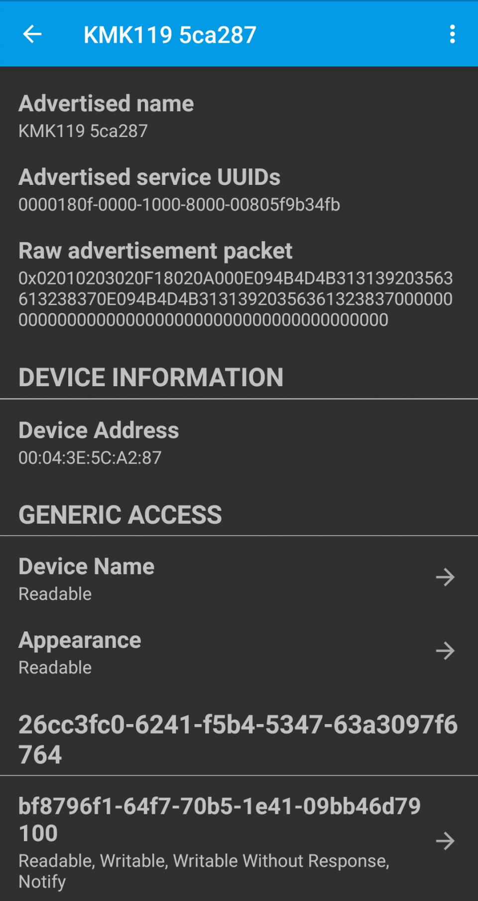
Select the "Readable, Writable" service on bottom of screen.
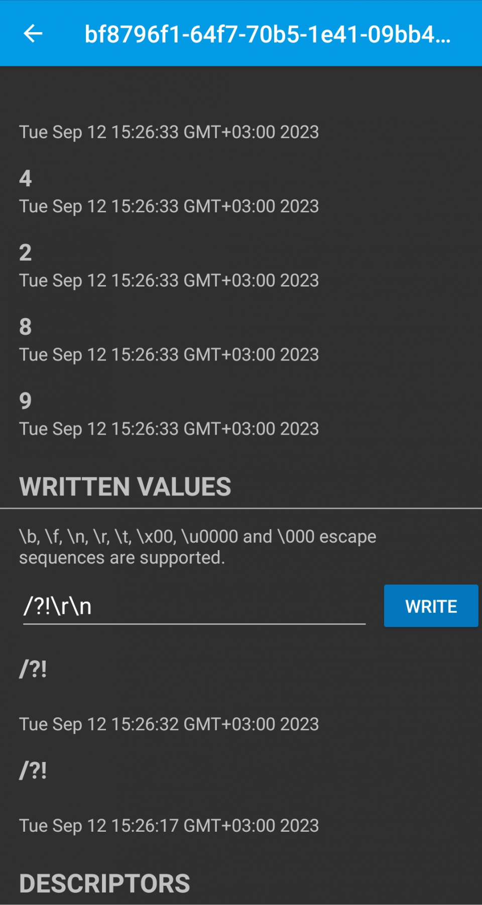
New window will be opened. Click "Subscribe" in this window and enter the command to send to meter. In this example we will send
/?!\r\n
Which is opening command for IEC62056-21 Mode C.
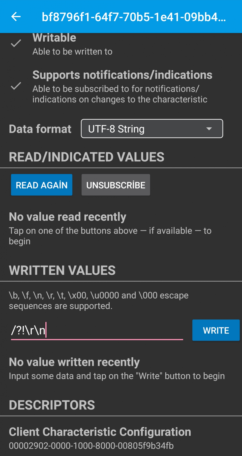
Place the probe on optical interface of meter and click "Write". Application will show meter response
In order to configure Bluetooth settings, additional optical probe is needed. So user should use USB service probe and place them against to each other
Here is a video example on how to configure Bluetooth Low Energy (BLE) and read an IEC meter
KMK119 can be connected with any Bluettooth device such as mobile phones. It support communciation with mobile software such as Zrobo developed by our company and available free in Google Play.
Click to go to product page of ZRobo
Here is a video for application:
NOTE: In this application, it is also shown that KMK119 can be used to read meters via cable a swell (without powering up the device and enabling the USB) in addition to Bluetooth communication . This is for usb+ versions only and must be ordered specifically.
KMK119 can run 4 different modes in same device and those mdoes can be changed via switch
Mode 1: 300-7E1 IEC auto Mode C.
Mode 2: 300-7E1 IEC start and change to DLMS/COSEM ( 300-8N1 IEC start version also available which is needed for some meter applications)
Mode 1 -2: When user have a software that cannot be changed like a software from meter manufacturer, this auto protocol dedection mode will help user to use probe with that software. Mode 1 is for IEC612056-21 protocol, Mode 2 is DLMS protocol with IEC62056-21 opening ( There are 2 version with data type 7E1 and 8N1, users can select based on their need)
Mode 3: Fixed 9600-8N1 communication
Mode 3: Constant baud and data type version can be used with software that needs constant baud and data type
Mode 4: Custom command mode. In this mode the device will work transparently and gets some commands from user.
Mode 4: When user has it s own software developing capacity, this mode can be used to integrate commands to software and use the probe in full functionality. Working modes explained detailly in "Chapter 2: Working Modes".
The upmost LED will turn ON when the probe is working in Mode 1 and lower most LED will turn on when the probe works in Mode 4. The other LEDs will turn ON in turn when Mode 2 or Mode 3 is active.
Here is a video for application for Mode 1 and Mode 4:
 download PDF